CFRP suspension pushrods
Team Bath Racing Electric, TBRe26
| ELEMENT | ROLE | NOTE |
|---|---|---|
| Pushrod CFRP conversion | DESIGNED | sized with own load tool |
| Shim adjustment mechanism | DESIGNED | |
| Suspension CAD assembly | DESIGNED | every member integrated |
| Toe and tie-rod turnbuckles | DESIGNED | |
| MATLAB load solver | DESIGNED | member forces, clevis shear and pull-out, across the load cases |
| ANSYS FE, static structural and eigenvalue buckling | DESIGNED | mesh sensitivity on the governing cases |
| Manufacturing drawings and build documentation | DESIGNED | |
| Bonded joint method | INHERITED | team composites R&D, prior year |
| Clevises and base inserts | INHERITED | pre-existing design |
| Member manufacture and physical testing | TEAM |
Requirement
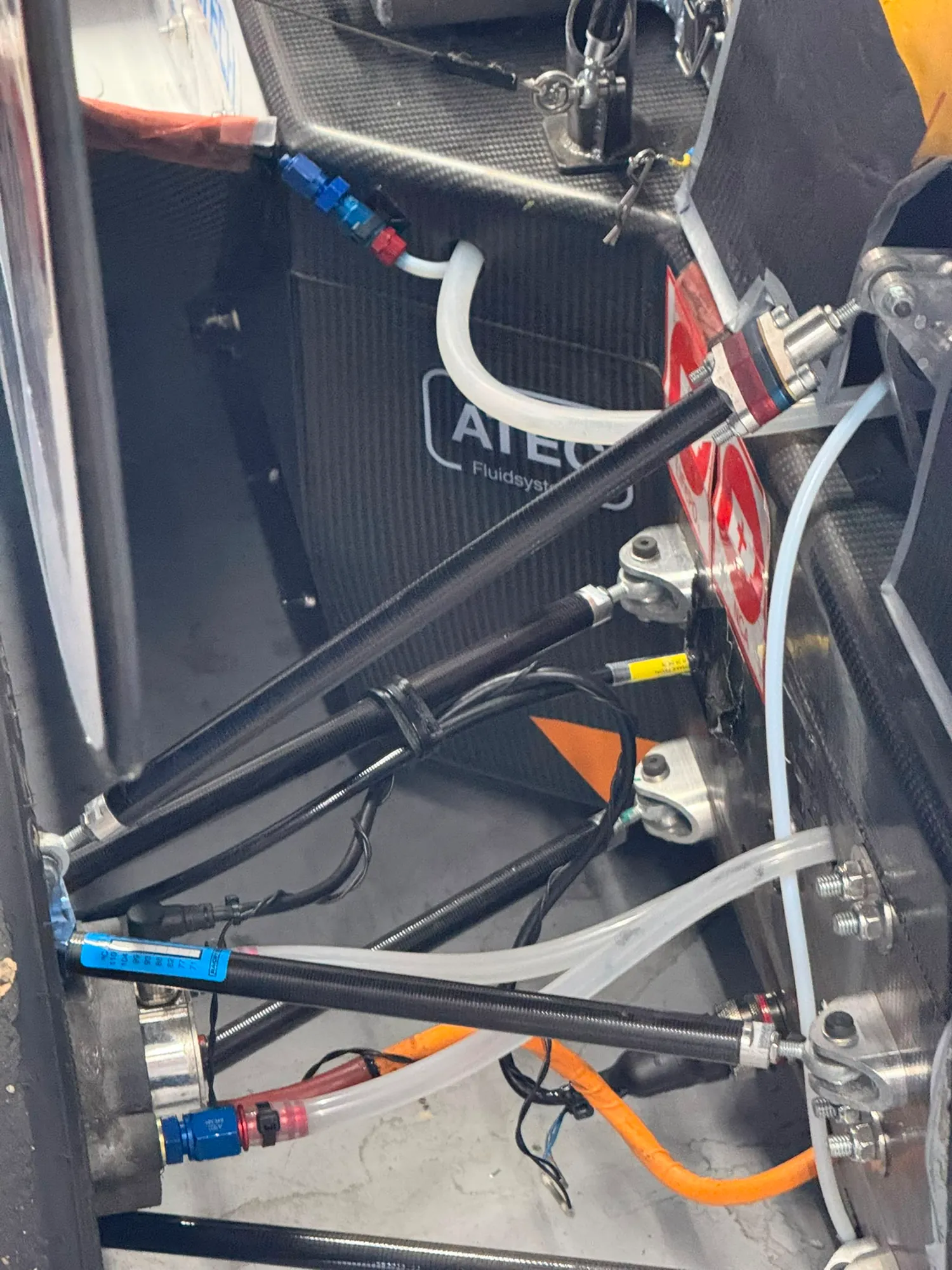
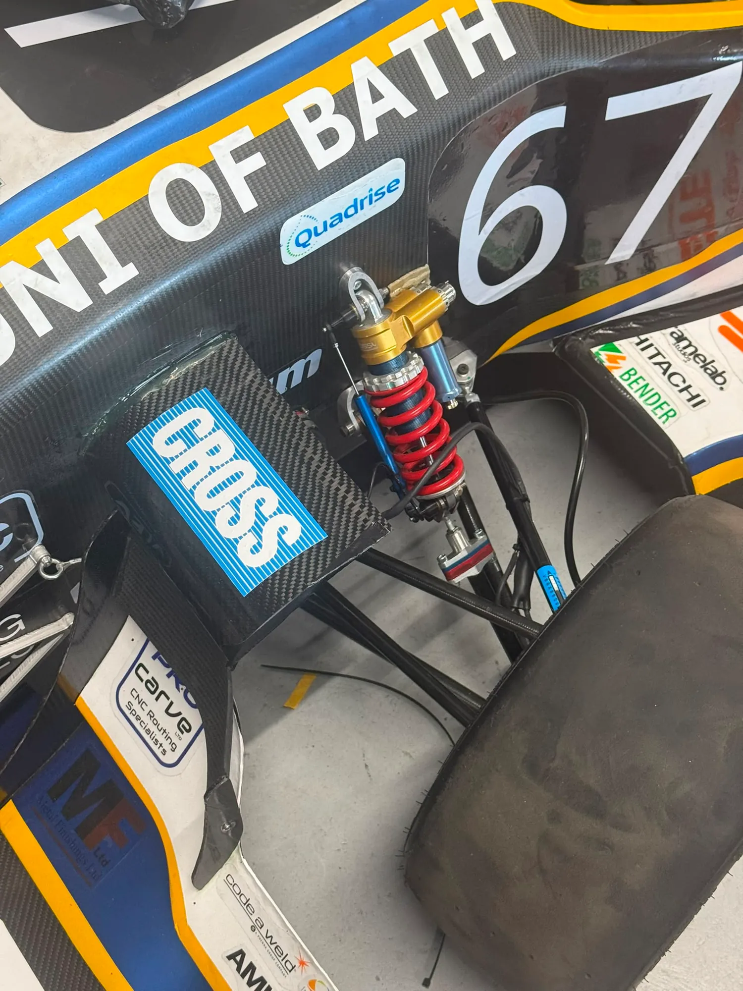
The team priority for TBRe26 was mass, across the whole car, and the steel suspension members were identified as a place to find it. Suspension members are effectively unsprung, to a degree set by their geometry, and pushrods sit at the top of that scale: both ends move with wheel travel, so nearly every gram counts as unsprung mass. Unsprung mass is the expensive kind: removed, it cuts tyre contact-patch load variation disproportionately compared with the same mass taken from the sprung chassis. The other requirement came from the garage. The previous pushrods were tedious to adjust on the car, and setup time is track time. The brief reduces to one line: much lighter, similarly stiff, adjustable in minutes. The front kinematics carried over from the year before; the rear was redesigned around the new chassis and independent roll and heave control.
Loads
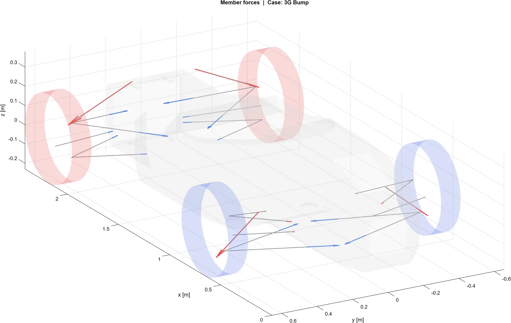
A MATLAB tool resolves suspension member forces from contact-patch loads for each defined load case, then the clevis shear and pull-out loads that size the connections. Sizing uses the envelope across cases, so one tube and one joint design covers all four corners.
The tool starts where the load starts, at the contact patch. Each load case applies a set of tyre forces, and the tool resolves them along every member's unit vector to give the axial force in each one. Run the full case set and the picture is complete: the maximum tension and compression every member will see, which case governs it, and what each member must be specced to carry. Clevis shear and pull-out came later, an extension built for the chassis team so they could read their own limiting cases from the same tool. The rear pushrod clevises are the one gap: the rear dynamics design was not finished when the tool was written, and the rear pushrod forces were low enough for me to judge that shear and pull-out on the rear shelf would not be limiting.
| CORNER | MEMBER | RESULTANT N |
|---|---|---|
| FL | Up-Fore | 271 |
| FL | Up-Aft | 107 |
| FL | Low-Fore | -1,734 |
| FL | Low-Aft | -1,563 |
| FL | Push/Pull | 3,554 |
| FL | Tie/Toe | 110 |
| FR | Up-Fore | 271 |
| FR | Up-Aft | 107 |
| FR | Low-Fore | -1,734 |
| FR | Low-Aft | -1,563 |
| FR | Push/Pull | 3,554 |
| FR | Tie/Toe | 110 |
| RL | Up-Fore | -1,302 |
| RL | Up-Aft | -1,639 |
| RL | Low-Fore | -285 |
| RL | Low-Aft | -546 |
| RL | Push/Pull | 4,632 |
| RL | Tie/Toe | -304 |
| RR | Up-Fore | -1,302 |
| RR | Up-Aft | -1,639 |
| RR | Low-Fore | -285 |
| RR | Low-Aft | -546 |
| RR | Push/Pull | 4,632 |
| RR | Tie/Toe | -304 |
The GUI earns its keep twice. It shows how force distributes through the car in a given load case, which was interesting learning in itself, and frankly it looks cool. One episode from before this tool shows why the loads get computed at all: all members originally shared one tube size, and when the front lower wishbone loads came through, the tube went up a size so the members would not buckle. That decision was not mine, it came out of the older solver this tool was built on, but it is exactly the kind of call a load picture exists to force. For TBRe27 the pushrods are being strain gauged, which should show how representative the tool's values actually are; section 6 carries that plan.
Design
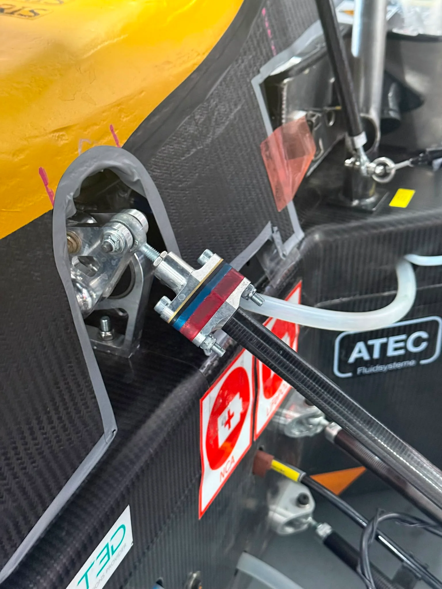
Each pushrod is a CFRP tube with bonded metallic end fittings: a threaded insert at the rocker end and a clevis at the upright end. Length adjustment is shim-based: a ground shim stack under the clevis shoulder sets pin-to-pin length without disturbing the bonded joints.
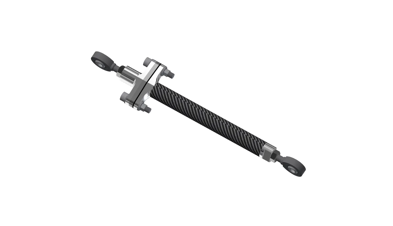
Manufacturing drawing withheld until cleared for publication.
Alongside mass, the brief was adjustability, and the previous car explains why: a circular shim arrangement with one of the bolts effectively blocked by tool access once the rod was on the car, which made every length change extremely tedious. This design answers that twice. The shims are binary, 1, 2, 4 and 8 mm thick, so four parts set a stack to exactly the length required; and the hole spacing is deliberately oversized for tool access, generous enough that it comes down next season. The insert bond length is on the same list: the tube, not the bond, sets the member's failure load, so the joint has area to give.
The first version went further. Its shims were open-slotted and lockwired, so a length change needed nothing more than backing the bolts off and pulling the lockwire: shims slide in and out with the pushrod still on the car. The FEA alone was not sufficient to sign that off, and there was neither the time nor the budget to prove it in hardware, so the car runs plain holes instead. Adjustment now means both bolts fully out, the corner supported while the pushrod is disconnected, shims changed, bolts back in. Slower, but conservative. I still think the slotted version works: the FE result that counted against it may say more about the model than the part, since the bolt preload was set at 5 kN, a level a bolt tightened by hand with an Allen key would never actually see. It is on the list to revisit for next year.
Analysis
Completed FE covers the metallic adjustment hardware: shim stack, threaded inserts and clevis details. Runs are static structural and eigenvalue buckling, with mesh sensitivity on the governing cases. Linear eigenvalue results overpredict buckling load; quoted margins account for this.
Manufacture and test
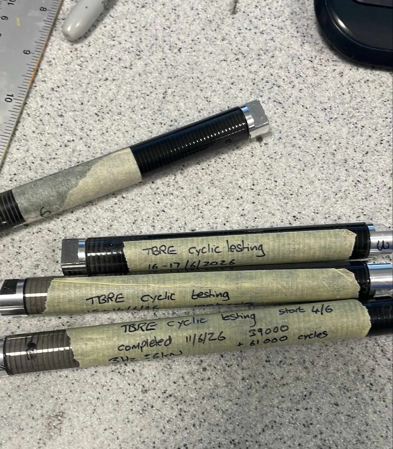
Manufacture and testing were the team's, the responsibility of our head of composites research; I was part of setting the tests up, not leading them. The specimens were representative members, tube and bonded end fittings without the adjustment hardware. The failure test reached 27 kN, and what failed was the carbon tube, not the bonded joint. In fatigue, the member survived 100,000 cycles at 6 kN.
Next
FE of the as-tested member against the raw test data, then the validated laminate model carried into the full pushrod assembly. Published when complete.
TBRe27 brings measurement into the loop: strain gauges on all four pushrods, with the wider aim of a fully instrumented front and rear corner. That gives the load tool something it has never had, measured member loads to answer to, and lets members be sized against what the car actually experiences rather than what the model predicts. My remit next year is the rear: leading the refinement of the rear dynamics and the mechanical improvement of the rear inboard suspension, with the rear kinematics carrying over. I will also help implement the new front kinematics, and keep refining the work on this page.